Today the MFRC522 RFID reader I ordered some weeks ago arrived. Using it with an Arduino proved to be pretty easy after I found this blog post.
Today the MFRC522 RFID reader I ordered some weeks ago arrived. Using it with an Arduino proved to be pretty easy after I found this blog post.
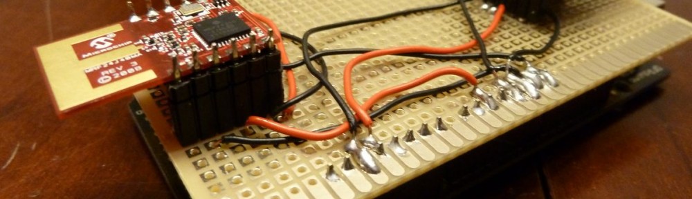
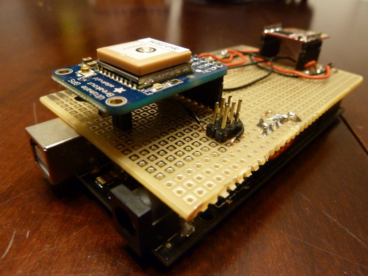
So, the prototype is working. Not very beautiful, and the soldering sucks, but it works and it spares me from putting a breadboard in the boat again. Below the circuit board is the Arduino Mega which is currently operating as the test platform, on top of it are the MRF24J40MA wireless module and the Adafruit Ultimate GPS receiver.

Now I only have to build something similar for the bluetooth bridge, make some adjustments to the software and I’m good to run another life test on a lake (without having to fear that the boat wanders out of bluetooth range).
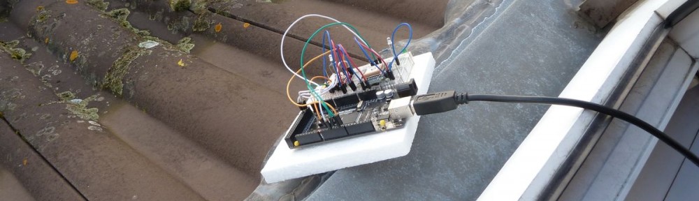
So, I got my wireless bridge working. Here are pictures of my setup, an Adafruit Ultimate GPS module happily sending its location to my Android phone.

The Arduino sitting out of my window on the roof is connected to the GPS receiver and one of the two MRF24J40MA modules. Continue reading MRF24J40 Bluetooth Bridge
So, after some trial and error I managed to interface the MRF24J40 modules with two Arduinos and have them exchange data.

This looks more complicated than it is. Continue reading MRF24J40 and Arduino

One mrf24j40 module connected to an Arduino Nano, the other one to an Arduino Mega … looking awesome, but not yet working.
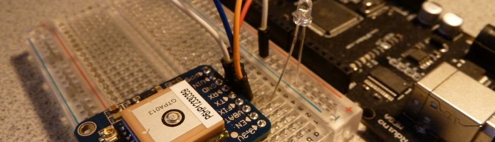
In the last couple of weeks some interesting new toys I ordered arrived. First, two MRF24J40MA wireless transceivers. I actually had them lying around for a while now, but I wanted to wait until the GPS receiver arrived as well before I start playing with them.
I did some updates to the software of the wordclock. It couldn’t really cope with interference, and since it relies on updates from the DCF77 receiver every minute it doesn’t really work as soon as something interferes. I was a little surprised how much the signal is affected by everyday things. TVs, for instance, at least the CRT kind, which is still widely used. My main problem turned out to be the lights of my aquariums, which are neon tubes. They too affect the radio signal, which I confirmed with a “normal” radio controlled clock.
To account for these issues I modified the code to display the time from the Arduinos internal clock. This internal clock is not very accurate, from what I gathered on the Internet it is off by a couple of seconds after only a day or so. For that reason I use the radio clock signal to set the internal clock when it gets a clean signal, which should be every day at night when all interfering sources are turned off. That way the RTC chip i mentioned earlier in this post is not really necessary.
I updated the main article about the clock to reflect these changes, the new software is available for download there as well.
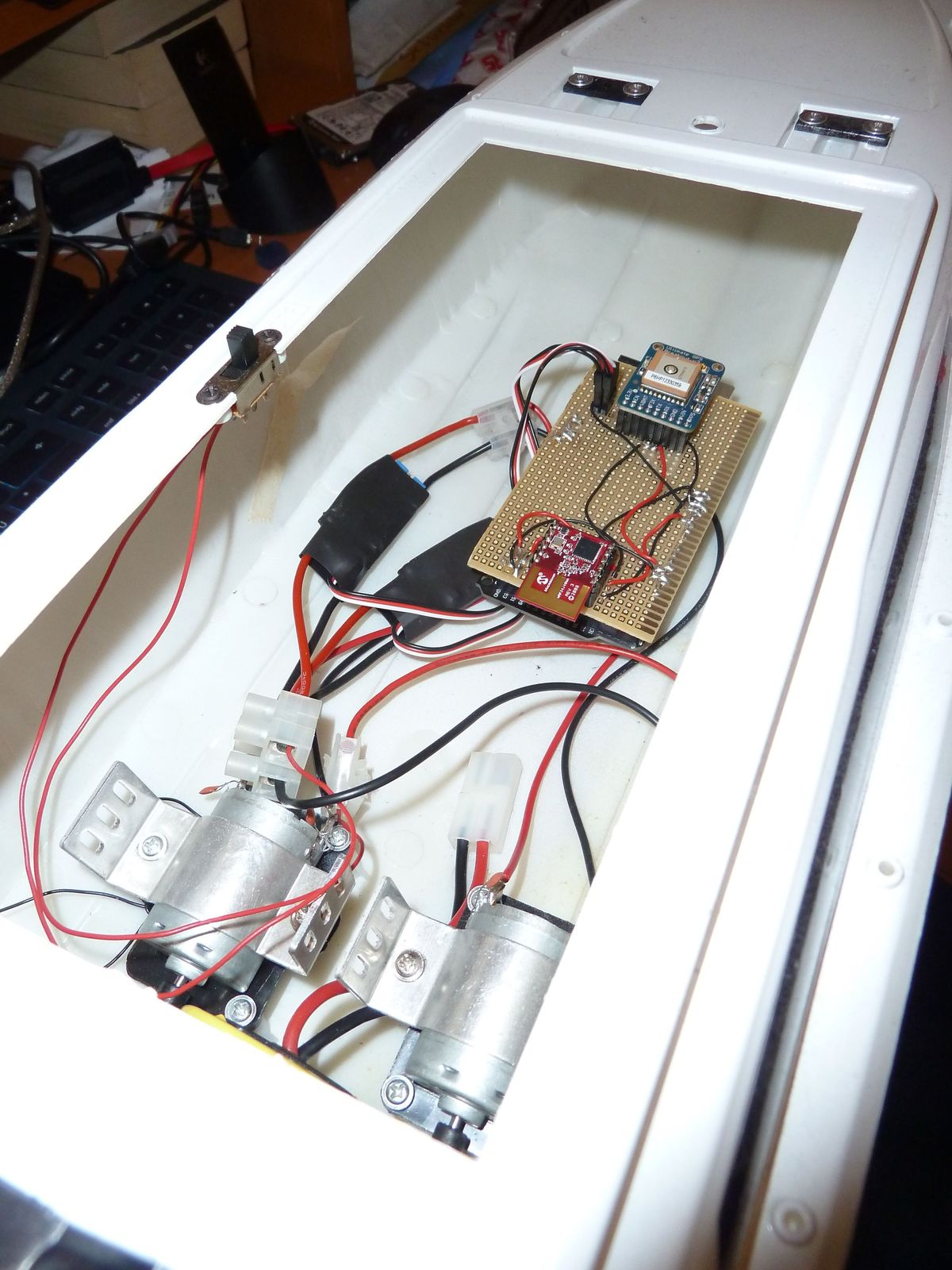
 So, I finally managed to get the basics done and put them together. First were the ESC for the motors. I had ordered two Turnigy 30A ESC for brushed motors from HobbyKing and it took “only” six weeks for them to be delivered. I guess it was my fault, ordering right before the chinese new year, when nobody seems to work for the next two weeks. At least neither my order was processed nor my questions were answered by the support. Anyway, they arrived eventually and I connected them to the motors, the battery pack and the Arduino. Continue reading Controlling the boats motors from Android
This weekend I did some final troubleshooting on my first wordclock. I had the problem that every time the display was updated all LEDs flickered a little. Very annoying, especially when there is no change.
Finally it hit me: I had connected the 74HC595 chips to the pins 1, 2 and 3. I guess I just wanted to “start” somewhere. What I didn’t account for, is that Arduinos serial port is accessible via pins 0 and 1. They are even labeled with RX and TX. So, everytime I sent data to my computer over the serial line it also went out on pin 1, which is connected to the 74HC595, hence the flickering.
Long answer short: Don’t use pins 0 and 1. Except for serial connections of course.
After six weeks of waiting the electronic speed controllers I ordered from HobbyKing finally arrived.

I just hooked it up to an Arduino Mega and a motor and the battery pack of the boat to do some preliminary testing, so there isn’t much to show yet. I’ll post more when I’ve done some real stuff with it.