Today the MFRC522 RFID reader I ordered some weeks ago arrived. Using it with an Arduino proved to be pretty easy after I found this blog post.
The crucial part from this blog post was the pin map … every other blog post or forum thread was about software, nobody noted how you have to wire it up. The Arduino code provided on this post is a little confusing … I have the impression it is a chinese translation of a code snippet I found on another site before, which only merged the code from module and sketch from this GitHub repository into one sketch file, making it extremely difficult to read. The code from Miguel Balboa on the other hand, while much more tidy is lacking information on how to use it.
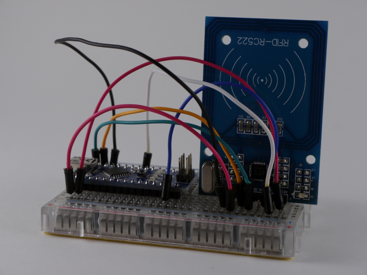
So, this is how I wired the RFID reader to the Arduino, using the notations on the PCB:
| MFRC522 | Arduino |
|---|---|
| SDA | 10 |
| SDK | 13 |
| MOSI | 11 |
| MISO | 12 |
| GND | GND |
| RST | 5 |
| 3.3V | 3V3 |
This way I was able to use Balboas sketch and module without modifications.

Update 27.11.2013
In the comments some people asked how they can make the RFID module work with other Arduino variants. It is really difficult to help with hardware I do not possess myself, so you can only hope that somebody else reads your comment and can help you. You will get much better help when you ask on a dedicated community site, I can highly recommend the Electrical Engineering Stack Exchange site.
Hello, thanks for the post!
I´ve got excatly the same RFID reader connected to my Arduino Leonardo but unfortunatelly it does´t work.
I tried different tutorials but the results stay same.
Do you have any idea? Any chance my reader is broken? (LED on it is working)
Thanks!
So far I only tried what I described in this post. There are two things that come to mind: Make sure you are not using pins on the Arduino that are already in use. The serial connection to the PC for example uses two pins as well. Second, are using RFID tags that came with the reader? Not all tags are compatible.
It’s been a long time since you wrote the comment, but I encountered the same problem, then I learned that the computer could not see the Arduino Leonardo as an input device. This may be the problem.
Yeah, I considered both options.
I also tried to connect reader to ICSP with different code without succes.
There must be something I am missing otherwise I am moron.)
Thanks for this pointer!
Pavel, the trick is using the correct SPI pins — on the Leonardo, they are indeed on the ICSP port. http://www.pighixxx.com/downloads/arduino-leonardo-v2/ is a good diagram of what pins mean what on that and other connector. The pins to use for the Mega2560 or the Leonardo are:
MFRC522 Mega Leo
—————————
SDA 10 10
SCK 52 ICSP3
MOSI 51 ICSP4
MISO 50 ICSP1
GND GND GND
RST 5 5
3.3V 3V3 3V3
I (just to be safe) also ran each line through a level converter, to make sure the MFRC522 isn’t getting over 3.3v on the data lines.
Thanks! You saved my day, finally it reads the chip.
53 as SDA is also ok, but the other pins for the Mega are just wrong in the example code.
please, can you share your code and your conections?, I have been tried 3 days but I cant got anything, I have the Arduino Leonardo, please, please
Can you please tell these pins for arduino due.
I can’t get my MFRC522 to work with my Arduino Uno with Miguel Balboa’s code. I a MFRC522 module that is exactly the same as shown in the pictures, but I bet the problem might be with the Arduino. I’m buying an Arduino Nano, but I wonder what version does your Arduino Nano happens to be? Version 3.0?
My Nano is not an original, it’s a clone of an Arduino Nano 3.0 (the creator calls it a “Quitos Nano”).
I’d be buying cloned (or I’d call it pirated, LOL) Arduino Nano V3.0 as well. I hope it’ll work with the RC522 module. I’ll keep you posted. Thanks for your reply.
Hi Dear,
i need RFID tag writing example steps………
hi all.
can any one tell me the correct pin connection between RFID RC 522 with Arduino mega 2560 and the code???
thanks
if u got ur answer by now please tell me .im stuck at the same point.
thnk you 🙂
Hi… I am working with mfrc522 RFID and arduino uno…. I connected the RFID with uno as suggested by Miguel Balboa’s code in GitHub ( read me) and tried to see the card information in serial monitor…..but to my disappointment I could see nothing… Can anyone help please?
hello any example source code for write tag,
example 1 tag card can on led, but another tag cannot do that
thank alod
Hi, I’m Trung. I need Protocol (Structure frame message) of MFRC522 for Ardunio. If you know, then you can tell me what is not ? Thanks you !
hi i have this working great but have you a vertion of code to ouput to a pin so it can be made to operat a lock circuit with a three second time delay
then it is a practical system best regards kev
Thanks for this very helpful article and a link to the source code!
I have one remark regarding the compatibility of 3.3V and 5V logic, though.
According to the NXP data sheet section 11 (Limiting values), the input voltages on the pins should be at most 0.5V above the supply voltage, which in turn can be at most 4.0V. With a 3.3V supply voltage, the maximum input voltage would be 3.8V.
According to the ATmega328 data sheet at http://www.atmel.com/Images/doc8161.pdf section 28.2 DC Characteristics, VOH (output high voltage) is defined as at least 4.2V, with 5V supply (used on the Arduino Uno). Because VOH>4.2V>3.8V, we seem to be violating the NXP MFRC522 specification.
So, it seems that to be on the safe side, you should either use a level converter such as the CD4050 or some resistors on the Arduino output pins, or convert the Arduino Uno to run with a 3.3V power supply, as described at https://learn.adafruit.com/arduino-tips-tricks-and-techniques/3-3v-conversion
On the Arduino forums, I found one thread that lead me to believe that running the Arduino Uno with 5V could in practice damage the Funduino RFID-RC522 module. The posted source code snippet did contain some minor errors, though.
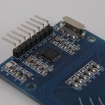
The board in your pictures looks similar to mine (mine is red, but the component layout looks the same). While there are some resistors and capacitors next to the chip and the connector, it seems that on my board, the connector is directly wired to the chip, requiring 3.3V I/O connection. This feels a bit strange, because all other parts in my boxed kit seem to be 5V compatible.
Hello , I want to consult one question.
I use RC522 and arduino uno and I want to use Xbee to transport the data to computer with wireless.
How can I write my program?
Thans for teaching
I just bought a cheap MFRC522 board from Hong Kong and tried to run it with my Arduino Uno, but it doesn’t work. As Marko Mäkelä said, the 522 data sheet http://www.nxp.com/documents/data_sheet/MFRC522.pdf says only 3.3v on the data pins (as well as the power supply) so I suspect thats why it doesn’t work with the Uno. Some folk clearly got the MFRC522 working but it isn’t clear if they all provided 3.3v on the data pins somehow (eg. using a 3.3v Nano) or whether anyone used 5v and just got lucky that it operated so way out of spec – I suspect not.
I then tried adjusting the voltage with resistors but still no joy, not sure whether I’d done that wrong or more likely the 5v had fried the chip. So I suggest:
WARNING: DON’T USE THE MFRC522 DIRECTLY WITH 5V ARDUINOS.
I have been using the RFID-RC522 directly with an uno for some time now. The data lines go directly into the 522. I’ve been powering it off 3.3 however.
I had tried attaching series resistors for some primative level conversion on the scl/sda but when I did it stopped working. Resistors removed, worked fine, no smoke.
I would like to move it to an ardweeny tonight but that does not have a 3.3v onboard, just passes VDD through which is typically 5v. (can be 3.3, but most of my support hardware runs at 5) I have a few extra 522’s but don’t feel like frying one today. I’ve seen more than one person tell me what I’m doing right now, running 5v digital right in from the uno, should fry it. I’ve tried it with mutiple 522’s from two sources and no problems with any of them, so I doubt I just happen to be lucky on my tolerance here.
So I think too many are giving advice without hard facts, so I don’t know who to believe as to whether or not I can VDD it with 5v. I’ll keep looking. It would be a lot easier for me to just go with 5 rather than add parts to gen some 3.3 just for the 522.
The link I posted is to the manufacturer’s data sheet for the chip – if that doesn’t count as hard facts I’m not sure what does 🙂
Data sheet says 3.3V power and max around 4 V on the data lines, so it sounds like either you have been very lucky so far or perhaps the boards you have used, by design or accident, take care of the differences. The question is: are you feeling lucky today?
Looks like some folks get away with it, but I didn’t. You have been warned. http://forum.arduino.cc/index.php/topic,233768.0.html
Hello everyone,
For those who have problems with the RFID reader / writer.
All pins should have a maximum of 3.3 volts. The data pins at max. 3.3 volts.
The code works fine, have an Arduino Pro Mini put on 3.3Volt and it worked immediately.
5 volts on arduino the RFID is not working anymore!!
Regards, Michel.
i want to connect two rfid reader in same board how should i do?
hey there .I m trying to work with arduino 2560 and rfid rc522
please tell me how to configure it
I started a project with adruino RFID card. The card I got is ref. mfrc522 of SainSmart.
pins are different from the ones in most popular projects.
I got only pins : 3.3v, scl, sda, gnd, EA, rst, irq
there is no such pins MOSI; MISO present in most projects);
Thanks for help.
Nice article! thanks!