
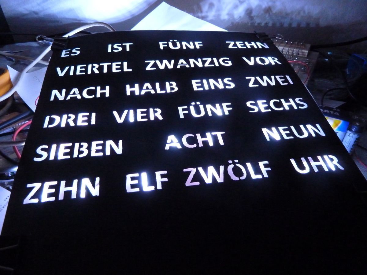
The wordclock shows the current time in actual words, in a manner as one would say it when somebody asks for the time: “It is a quarter to five”. It has all words needed to tell the time, the right words are lighted.

The clock consists of a paperboard front, with words cut out with a crafting knife. Behind is a translucent paper which disperses the light from the light-emitting diodes which illuminate the single words.
This page is only a brief description of the current state. If you are interested in the details and in the process of making it, feel free to browse through the posts in its category.
Electronics
The electronics part consists of the following: The core is an Arduino, which reads the current time from a DCF77 radio receiver. The DCF77 signal contains the current time and date and is broadcasted near Frankfurt, Germany and can be received about 2000km around this location. So, if you live outside this area, this solution will not work for you.

Also attached to the Arduino are three 74HC595 chips which are used to address the LEDs. Some pictures from testing and the circuit board I made to connect everything.
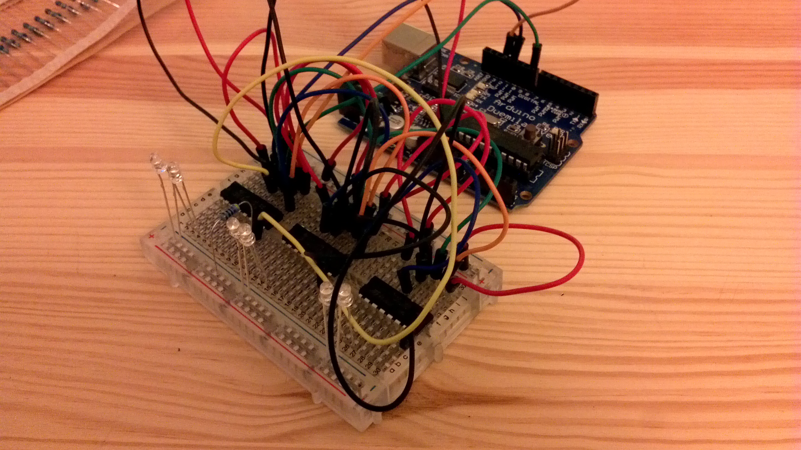
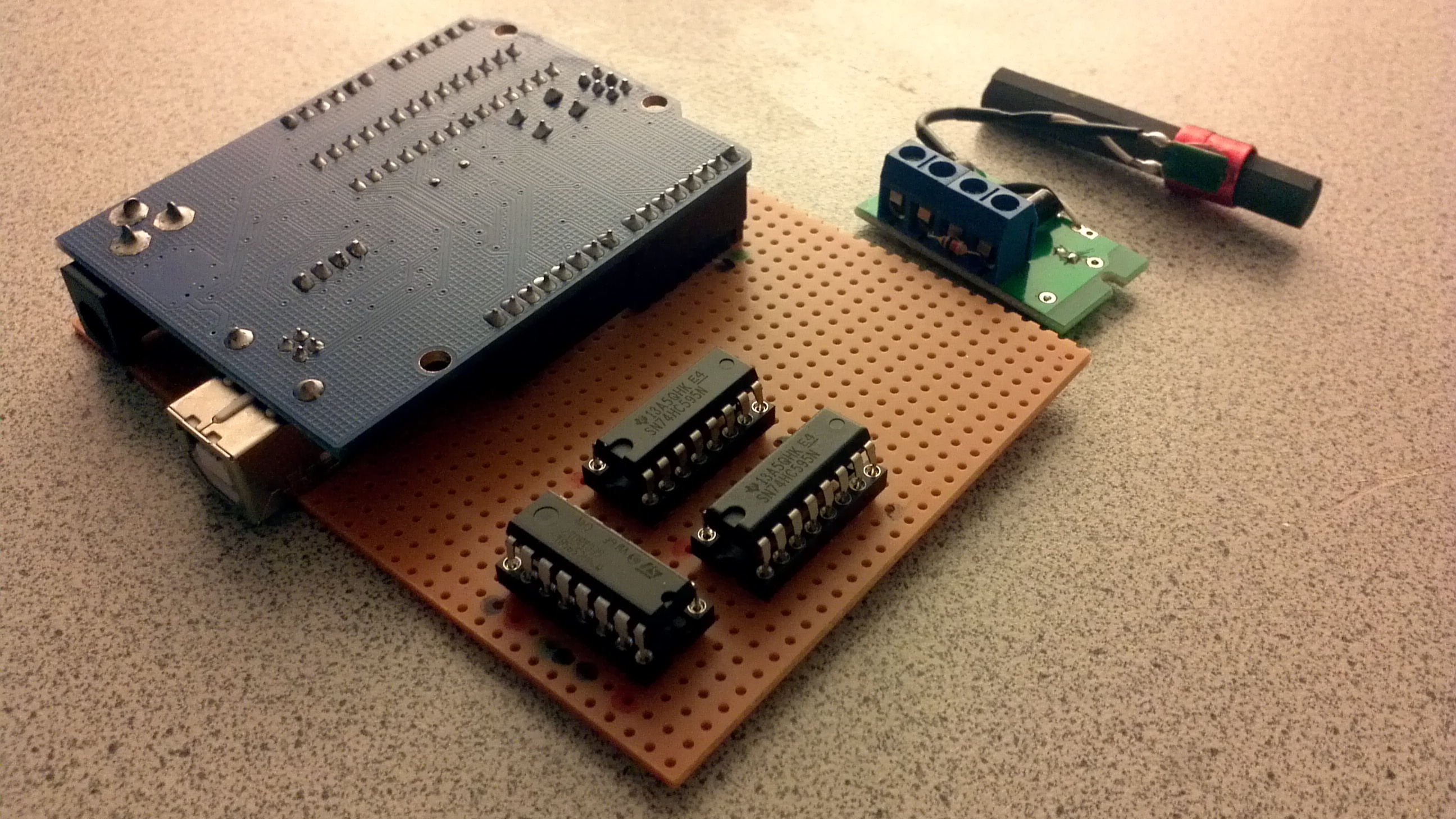
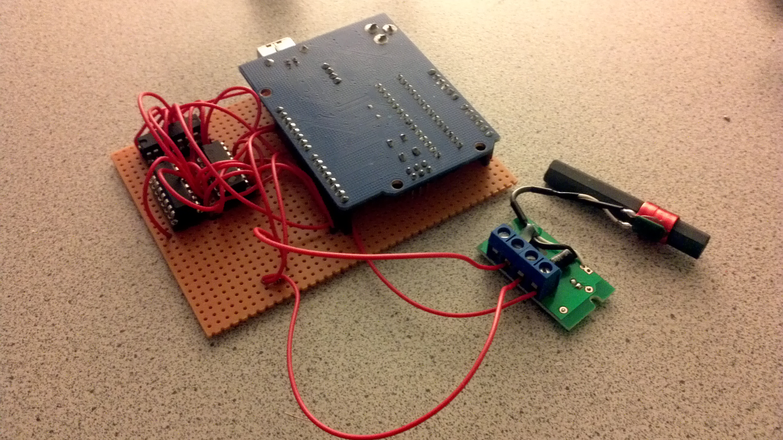
The board is admittedly ugly, even more so, because I only had wires in red available. I plan to make a real circuit board for it in the future.
The crafted part
To cut the words out of card board I printed them inverted on a DIN A3 sized paper. I used spray glue to glue it on the card board. Then I used a crafting knife to cut out the characters.


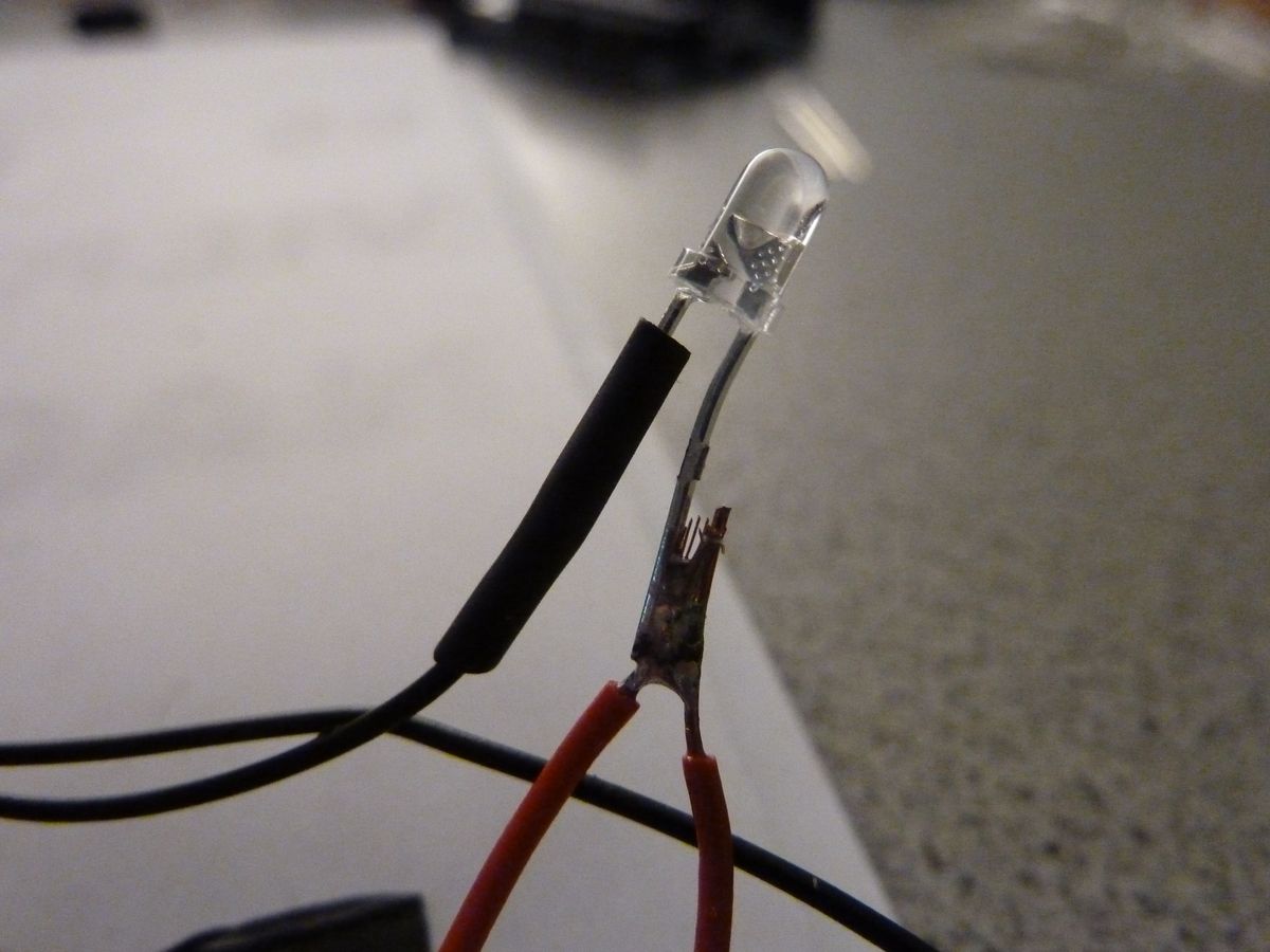
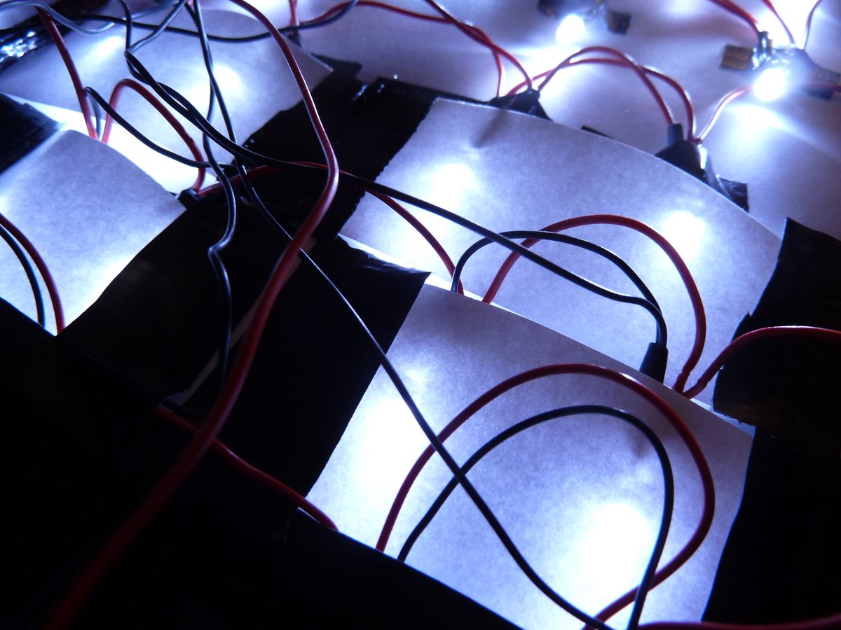
I used simple duct tape to glue the LEDs behind the cutouts on translucent paper. Then I soldered cables directly to the LEDs.

The LED pins are isolated with heat shrink tubes, the long wires are soldered to the shift register chips on the circuit board.

To isolate the words better from each other I used more duct tape to attach pieces of paper behind each word.


I found a framed mirror at a local hardware store which hat perfect measures for the clock, so I removed the mirror, drilled a hole in one side for the USB cable that provides the power. The back plane was mounted with staples, so I just placed the clock in the frame and remounted the back plane behind it with a staple gun.
The Software
You can download the current version of the software here: Wordclock Version 0.4 (Updated 20.03.2012)
Version 0.4 adds usage of the Arduinos internal clock.
- Version 0.2: Wordclock.ino (15.01.2012)
Some things to note:
- g_pinCommLatch, g_pinData and g_pinClock are the digital pins where the shift registers are connected to the Arduino.
- DCF77 is the analog pin where the DCF receiver is connected.
- Don’t make the same mistake as me and use pins 0 or 1 on your Arduino for any of those!
- I accidently switched two cables when I soldered the LEDs to the shift register chips. It was easier to reflect this in the software than soldering the cables out and in again. So make sure you shift the right bits.
Room for improvement
- Find a better way to wire the LEDs. The current way is a mess. Maybe I can cut circuit board with lines down to stripes with two conductive lines.
- Create own PCB. Next time I’ll definitely etch my own circuit board.
- More even illumination. Mounting the LEDs sideways doesn’t make for a very good illumination since most of the light is lost. I’d have to find a way to mount the LEDs so the light shines directly towards the front.
- Better separation of the LEDs for each word
Credits
- J. M. Lietaer, for his code about decoding the DCF77 signal (link dead now)
- Torsten Amshove, for his code to validate the DCF77 signal (page is in german)
- Paul S. Randal, who shared how to use shift registers easily
Hi,
Great website and very useful! I’m also building a word clock, but I’m still in the early stages. I had similar trouble with noise in the DCF77 signal, so I tried to build a more robust library.
It is based on the sketch by Matthias Dahlheimer, but with some differences
Plays nice with the Time Library and setSyncProvider callback
Uses a single interrupt for signal-changed based triggering
More robust against noise: rejects the majority of incorrect spikes
More sanity checking on decoded time.
Can return UTC time, useful for timezone conversion
See, http://thijs.elenbaas.net/2012/04/arduino-dcf77-radio-clock-receiver-library/
and here the Thread I opened on the arduino forum:
http://arduino.cc/forum/index.php/topic,102039.0.html
I hope it doesn’t seem like I’m spamming, but I’m looking for people to give it a testdrive, so I can iron out the bugs (if there are any).
Cheers, Thijs
Looks interesting, I’ll give it a try the next time I’m working on it.
And I’ll definitely use your Fritzing part for the DCF receiver 🙂
Hi Gerald,
Really love this worldclock !
Great job !
J.M.
Link to the Arduino DCF77 Library
http://lietaer.be.dotnet39.hostbasket.com/arduino/Dcf77.zip
Example code using DCF77 Library:
/*
Author : J.M. Lietaer, Belgium, Europe – jmlietaer (at) gmail (dot) com
User level : Total Arduino Noob
Date written : March 06, 2010
Program : Example program for DCF77 Library
DCF77 – Read data from a DCF77 module and display date/time
System : Arduino Duemilanove ATMEGA328
Software : Arduino IDE 0018 on Apple Mac OS X 10.6.2
Tested with : Pollin DCF1 – article number 810054
Information : Please feel free to comment and suggest improvements
Released under : Creative Commons Attribution – Share Alike 2.0 Belgium License
*/
/*
Example of output:
– Result of calling getDateTime()
DCF77DATA 2010030661531CET
CCYYMMDDdhhmmTTTT
– Result of calling version()
DCF77VERS 0.1 beta
– Return of getDateTime() while capturing DCF77 data
DCF77POLL
*/
#include “Dcf77.h”
Dcf77 dcf77(1);
void setup() {
Serial.begin(9600);
}
void loop() {
const char *v = dcf77.getDateTime();
if (strcmp (v,”DCF77POLL”) != 0) {
Serial.println(v);
}
}
Hello there.
Is there any possibillity to get the Dcf77.h file?
I can’t find it any where.
The link from JM Lietaer gives an error.
I like to experiment with my DCF77 module and using a program from Elektor
Please any help is welcome.
Regards
I’m not quite sure, but I think it’s the official DCF77 library.