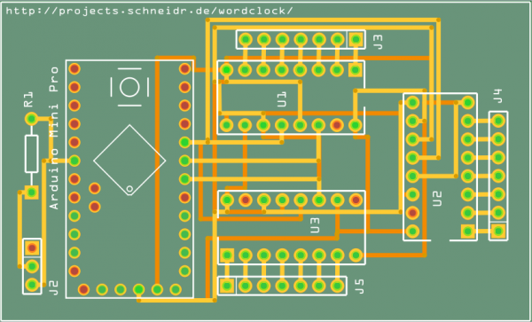
Yesterday I was playing with Fritzing to create a circuit board for the wordclock. Building it on the breadboard was easy, but the auto routing on the PCB-layout drove me nuts. Today I tried it again, loaded the file, repositioned the components on the circuit board a little and guess what … it worked on the first try. This is how the circuit board in the next version of the wordclock may look like:
It is designed for an Arduino Mini Pro, which is by far the cheapest Arduino variant I could find and which is sufficient for this purpose. U1, U2 and U3 will hold the 74HC595 ICs, J3, J4 and J5 will connect the LEDs. J2 is the connection for the DCF77 receiver.
I guess next I’ll have to learn how to etch my own circuit boards.
